
IFC 4×3 contains new specialized entities like IfcFacility, IfcBridge, IfcRoad, or even IfcBearing, IfcPavement, or IfcRail (not everything related to infrastructure has to be modeled with generic IfcBuildingElementProxy anymore). We also have IfcAlignment and resulting new ways of linear placing of geometries.
So how to implement these novelties in the actual IFC model? Let’s go step by step through a simple model schema and reveal that. I think it is a good exercise, not only to grasp the newest IFC4x3 possibilities but also to understand the structure of the IFC model “under the hood”.
Open your notepad (or anything for creating txt files), create a new file, save it with the “.ifc” extension, and let’s begin!
Header
First thing – header. It contains basic information about the file: name, time stamp, creator and a related organization, and used software/processor. It states also the data schema (the IFC version). Here, we use “IFC4X3_ADD2”, referring to the current official IFC 4.3.2.0.
ISO-10303-21;
HEADER;
FILE_DESCRIPTION ((”), ‘2;1’); FILE_NAME (‘Bridge model example’, ‘2024-10-14T17:42:13’, ‘Kamil Korus’, ‘AECO Evolution’, ‘Processor version’, ‘Software’, ”);
FILE_SCHEMA ((‘IFC4X3_ADD2’));
ENDSEC;
Project and units
IFC data is coded with entities. The entities can have various attributes. IfcProject is one of the basic entities. Its first attribute (like for many entities) is the unique global identifier, GUID. Next, IfcProject contains properties like name or description. Attributes values can have different forms, like texts or numbers (some values are optional and can be omitted with “$”). Attributes values can also refer to other entities. Then, the attribute value is a number (or numbers) preceded by hashtags (e.g., #2) referring to the number of a referred entity. In our example, #2 (colored to better recognize the linkage in the model code) links the IfcProject with a set of units declared for the model. (#14, #17) links the project with its geometric representation contexts, which we will define next.
DATA; #1=IFCPROJECT(‘0vGCH5MKb7IxXhcP$Yz3$a’,$,’Bridge project’, ‘This project is a simple example of modeling a bridge’,$,$,$,(#14,#17),#2);
#2=IFCUNITASSIGNMENT((#3,#4,#5,#6,#7,#8,#9,#10,#11)); #3=IFCSIUNIT(*,.LENGTHUNIT.,.MILLI.,.METRE.);
#4=IFCSIUNIT(*,.AREAUNIT.,$,.SQUARE_METRE.);
#5=IFCSIUNIT(*,.VOLUMEUNIT.,$,.CUBIC_METRE.); #6=IFCSIUNIT(*,.SOLIDANGLEUNIT.,$,.STERADIAN.);
#7=IFCSIUNIT(*,.PLANEANGLEUNIT.,$,.RADIAN.);
#8=IFCSIUNIT(*,.MASSUNIT.,$,.GRAM.); #9=IFCSIUNIT(*,.TIMEUNIT.,$,.SECOND.); #10=IFCSIUNIT(*,.THERMODYNAMICTEMPERATUREUNIT.,$,.DEGREE_CELSIUS.); #11=IFCSIUNIT(*,.LUMINOUSINTENSITYUNIT.,$,.LUMEN.);
Geometric representation contexts – containers for model objects
Geometric representation contexts can be perceived as containers for model objects. A project can comprise several contexts, e.g., 3D (“3” in #14) or 2D (“2” in #17). A context has coordinate systems (declared with IfcAxis2Placement and referring to a point in the model) and declared precision (1.E-05).
#12=IFCCARTESIANPOINT((0.,0.,0.));
#13=IFCAXIS2PLACEMENT3D(#12,$,$);
#14=IFCGEOMETRICREPRESENTATIONCONTEXT($,’Model’,3,1.E-05,#13,$);
#15=IFCCARTESIANPOINT((0.,0.));
#16=IFCAXIS2PLACEMENT2D(#15,$);
#17=IFCGEOMETRICREPRESENTATIONCONTEXT($,’Plan’,2,1.E-05,#16,$);
Local placement and basic directions
Next, we define local placement (to which we will refer when placing model elements) and basic directions. Note how IfcLocalPlacement refers to IfcAxis2Placement3D (#13) created before, which is eventually linked with the point 0,0,0 (#12). The local placement and basic directions are useful for further geometry modeling.
#18=IFCLOCALPLACEMENT($,#13);
#19=IFCDIRECTION((1.,0.,0.));
#20=IFCDIRECTION((0.,1.,0.));
#21=IFCDIRECTION((0.,0.,1.));
Spatial elements hierarchy
Next, we define the hierarchy of spatial elements. IfcFacility (#22) is the basic spatial container in this model. IfcRelAggregates and IfcRelContainedInSpatialStructure codes relationships – they enable aggregating elements or containers to another element or container. IfcRelAggregates with the number #23 attaches our IfcFacility to the IfcProject (#1), so IfcProject “contains” IfcFacility. Next in the hierarchy are IfcBridge (attached as part of the IfcFacility) and IfcBridgePart (attached as a part of the IfcBridge).
Once again, the entities can have various types of attributes. Some of them must take predefined values. These attributescalled enumerators. .GIRDER. in IfcBridge or .SUPERSTRUCTURE.” in IfcBridgePart are example sof such predefined values. The predefined values are part of the IFC documentation (example: IfcBridgeTypePartEnum).
#22=IFCFACILITY(‘3eRo4UYs96VvgzHYlN5rwP’,$,’Facility’,$,$,$,$,$,$);
#23=IFCRELAGGREGATES(‘1zjaZZpoz2EwQTKxCE3dQj’,$,$,$,#1,(#22));
#24=IFCBRIDGE(‘2pyXrKuJX2hROBEU2KQ1rq’,$,’Bridge’,$,$,$,$,$,$,.GIRDER.);
#25=IFCRELCONTAINEDINSPATIALSTRUCTURE(‘2PeVAh2uH2phENraW6lvHj’,$,$,$,(#24),#22);
#26=IFCBRIDGEPART(‘2N8pyojwb4Bgw07KZBEF3O’,$,’Superstructure’,$,$,#36,#55,$,$,.USERDEFINED.,.SUPERSTRUCTURE.);
#27=IFCRELCONTAINEDINSPATIALSTRUCTURE(‘1LqnXVBdfEMwYGj9_UUshh’,$,$,$,(#26,#30),#24);
Materials
Here, we declare a material and attach it to the superstructure using IfcRelAssociatesMaterial (we are referring to #26 which is the IfcBridgePart). The material is an example of semantic data. The material, similarly to other entities, can have attributes (omitted in the example), further increasing the data-richness.
#28=IFCMATERIAL(‘Concrete’,$,$);
#29=IFCRELASSOCIATESMATERIAL(‘295_zxIQT9QBPS_FCpe59Y’,$,$,$,(#26),#28);
Alignment
IfcAlignment, one of the crucial novelties.
The alignment refers to the “0, 0, 0” placement (#18). Its profile is defined with IfcProductDefinitionShape (#35). Modeling the profile starts with IfcPolyline (#31) comprising two points (#32, #33). IfcShapeRepresentation (#34) attaches the IfcPolyline to the IfcGeometricRepresentationContext (#14) and states the shape’s type (“Curve3D”).
#30=IFCALIGNMENT(‘2eDu6iXCn6qfh2qIv8t0P2’,$,$,$,$,#18,#35,$);
#31=IFCPOLYLINE((#32,#33));
#32=IFCCARTESIANPOINT((0.,0.,0.));
#33=IFCCARTESIANPOINT((20000.,0.,400.));
#34=IFCSHAPEREPRESENTATION(#14,$,’Curve3D’,(#31));
#35=IFCPRODUCTDEFINITIONSHAPE(‘Alignment shape definition’,$,(#34));
Placement
The IfcBridgePart (#26) that we have created before refers to a placement (#36). IFC schema gives numerous options for placement definition. The most basic is a placement in an unrelated point (Option 1). The next two options in our example are also based on points but in relation to the alignment curve. Option 2 uses IfcPointOnCurve to get a point on the alignment. Option 3 uses a new schema resource, IfcPointByDistanceExpression, to get a point with possible offsets from the alignment. Option 4 presents a concept of linear placement relating directly to the alignment curve.
Here is an important warning – unfortunately, not all the options are yet implemented by IFC software (e.g., viewers). So, sometimes, even though the geometry is properly defined, the viewer may not show it. Option 1, placing in an unrelated point, is the secure old way, recognized by the software.
| /* Option 1: placement with an unrelated point #36=IFCLOCALPLACEMENT($,#37); #37=IFCAXIS2PLACEMENT3D(#38,$,$); #38=IFCCARTESIANPOINT((0.,0.,-80.)); /* Option 2: placement with a point on the alignment curve #36=IFCLOCALPLACEMENT($,#37); #37=IFCAXIS2PLACEMENT3D(#38,$,$); #38=IFCPOINTONCURVE(#31,0.); /* Option 3: placement with a point in relation to the alignment curve #36=IFCLOCALPLACEMENT($,#37); #37=IFCAXIS2PLACEMENT3D(#38,$,$); #38=IFCPOINTBYDISTANCEEXPRESSION(IFCNONNEGATIVELENGTHMEASURE(1000.),0.,-80.,0.,#31); /* Option 4: linear placement in relation to the alignment curve #36=IFCLINEARPLACEMENT($,#37,$); #37=IFCAXIS2PLACEMENTLINEAR(#38,$,$); |
Superstructure cross-section
We begin to model the actual geometry, starting with the superstructure cross-section profile. The profile (#39) is defined by a closed polyline (#40) based on points (#41-#51).
#39=IFCARBITRARYCLOSEDPROFILEDEF(.AREA.,$,#40);
#40=IFCPOLYLINE((#41,#42,#43,#44,#45,#46,#47,#48,#49,#50,#51,#41));
#41=IFCCARTESIANPOINT((0.,0.));
#42=IFCCARTESIANPOINT((-3800.,-76.));
#43=IFCCARTESIANPOINT((-6750.,-17.));
#44=IFCCARTESIANPOINT((-6750.,-237.));
#45=IFCCARTESIANPOINT((-4300.,-356.));
#46=IFCCARTESIANPOINT((-3900.,-1100.));
#47=IFCCARTESIANPOINT((3900.,-1100.));
#48=IFCCARTESIANPOINT((4300.,-356.));
#49=IFCCARTESIANPOINT((6750.,-237.));
#50=IFCCARTESIANPOINT((6750.,-17.));
#51=IFCCARTESIANPOINT((3800.,-76.));
Superstructure geometry
The last step for defining geometry.
IfcFixedReferenceSweptAreaSolid (#53) is a geometric representation sweeping a profile along a curve; here, the cross-section (#39) is swept along the alignment curve (#31). The resulting geometric representation is “packed” with IfcShapeRepresentation (#54), further referenced by IfcProductDefinitonShape (#55). These classes are helpful in aggregating more elements into one – for example, one model object (e.g., superstructure) can be represented by more geometries. The product definition shape is referenced as an attribute of the IfcBridgePart that we have defined before, linking the superstructure with its geometry.
#53=IFCFIXEDREFERENCESWEPTAREASOLID(#39,$,#31,$,$,$);
#54=IFCSHAPEREPRESENTATION(#14,’Body’,’SolidModel’,(#53));
#55=IFCPRODUCTDEFINITIONSHAPE(‘Superstructure shape definition’,$,(#54));
Bonus: external data sources
We have created an IFC model with spatial elements and geometries. At the current IFC adoption level, these are by far the most popular features. But the IFC schema enables much more. For example, attaching external data sources.
We end our example with classes linking the model with a web SHM database using fcPerformanceHistory, IfcLibraryInformation, and the “linking” classes, defining relations.
#56=IFCPERFORMANCEHISTORY(‘2AKe$ZJ1bCxunXTKWapVSF’,$,
‘Superstructure performance history’,$,$,$,’OPERATION’,$);
#57=IFCRELAGGREGATES(‘0dSmTizeDBMREGS$lvAfsh’,$,$,$,#26,(#56));
#58=IFCLIBRARYINFORMATION(‘Superstructure performance database’,$,$,$,’
https://www.digitaltwin-database.com/0vGCH5MKb7IxXhcP$Yz3$a/2N8pyojwb4Bgw07KZBEF3O’,$);
#59=IFCRELASSOCIATESLIBRARY(’01mMvMoyvFJwH8aYXLKCjV’,$,$,$,(#56),#58);
ENDSEC;
END-ISO-10303-21;
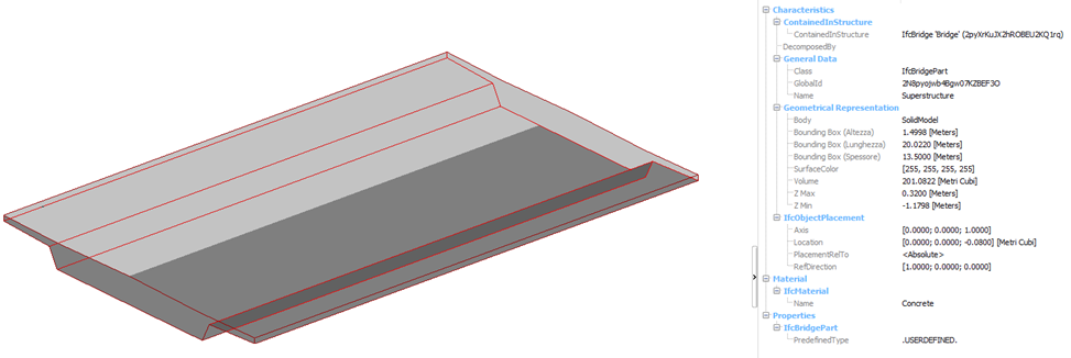
This is how our simple, but complete, IFC model looks like (visualized in usBIM.viewer+):
Summary
So, we have done it – step-by-step, “manually” created an IFC model.
Surely, the “manual” IFC coding is not so straightforward at first glance. Well, it’s a good thing we have software to model our projects, not only notepads to “write” them. Nonetheless, I think it is beneficial to know what is going on “behind the curtain”. It makes us more conscious and aware. And IFC – as I observe and hope – is gaining more and more importance.
Complete code of our model:
ISO-10303-21;
HEADER;
FILE_DESCRIPTION ((”), ‘2;1’); FILE_NAME (‘Bridge model example’, ‘2024-10-14T17:42:13’, ‘Kamil Korus’, ‘AECO Evolution’, ‘Processor version’, ‘Software’, ”);
FILE_SCHEMA ((‘IFC4X3_ADD2’));
ENDSEC;
DATA;
#1=IFCPROJECT(‘0vGCH5MKb7IxXhcP$Yz3$a’,$,’Bridge project’,
‘This project is a simple example of modeling a bridge’,$,$,$,(#14,#17),#2);
#2=IFCUNITASSIGNMENT((#3,#4,#5,#6,#7,#8,#9,#10,#11));
#3=IFCSIUNIT(*,.LENGTHUNIT.,.MILLI.,.METRE.);
#4=IFCSIUNIT(*,.AREAUNIT.,$,.SQUARE_METRE.);
#5=IFCSIUNIT(*,.VOLUMEUNIT.,$,.CUBIC_METRE.);
#6=IFCSIUNIT(*,.SOLIDANGLEUNIT.,$,.STERADIAN.);
#7=IFCSIUNIT(*,.PLANEANGLEUNIT.,$,.RADIAN.);
#8=IFCSIUNIT(*,.MASSUNIT.,$,.GRAM.);
#9=IFCSIUNIT(*,.TIMEUNIT.,$,.SECOND.);
#10=IFCSIUNIT(*,.THERMODYNAMICTEMPERATUREUNIT.,$,.DEGREE_CELSIUS.);
#11=IFCSIUNIT(*,.LUMINOUSINTENSITYUNIT.,$,.LUMEN.);
#12=IFCCARTESIANPOINT((0.,0.,0.));
#13=IFCAXIS2PLACEMENT3D(#12,$,$);
#14=IFCGEOMETRICREPRESENTATIONCONTEXT($,’Model’,3,1.E-05,#13,$);
#15=IFCCARTESIANPOINT((0.,0.));
#16=IFCAXIS2PLACEMENT2D(#15,$);
#17=IFCGEOMETRICREPRESENTATIONCONTEXT($,’Plan’,2,1.E-05,#16,$);
#18=IFCLOCALPLACEMENT($,#13);
#19=IFCDIRECTION((1.,0.,0.));
#20=IFCDIRECTION((0.,1.,0.));
#21=IFCDIRECTION((0.,0.,1.));
#22=IFCFACILITY(‘3eRo4UYs96VvgzHYlN5rwP’,$,’Facility’,$,$,$,$,$,$);
#23=IFCRELAGGREGATES(‘1zjaZZpoz2EwQTKxCE3dQj’,$,$,$,#1,(#22));
#24=IFCBRIDGE(‘2pyXrKuJX2hROBEU2KQ1rq’,$,’Bridge’,$,$,$,$,$,$,.GIRDER.);
#25=IFCRELCONTAINEDINSPATIALSTRUCTURE(‘2PeVAh2uH2phENraW6lvHj’,$,$,$,(#24),#22);
#26=IFCBRIDGEPART(‘2N8pyojwb4Bgw07KZBEF3O’,$,’Superstructure’,$,$,#36,#55,$,$,.USERDEFINED.,
.SUPERSTRUCTURE.);
#27=IFCRELCONTAINEDINSPATIALSTRUCTURE(‘1LqnXVBdfEMwYGj9_UUshh’,$,$,$,(#26,#30),#24);
#28=IFCMATERIAL(‘Concrete’,$,$);
#29=IFCRELASSOCIATESMATERIAL(‘295_zxIQT9QBPS_FCpe59Y’,$,$,$,(#26),#28);
#30=IFCALIGNMENT(‘2eDu6iXCn6qfh2qIv8t0P2’,$,$,$,$,#18,#35,$);
#31=IFCPOLYLINE((#32,#33));
#32=IFCCARTESIANPOINT((0.,0.,0.));
#33=IFCCARTESIANPOINT((20000.,0.,400.));
#34=IFCSHAPEREPRESENTATION(#14,$,’Curve3D’,(#31));
#35=IFCPRODUCTDEFINITIONSHAPE(‘Alignment shape definition’,$,(#34));
#36=IFCLOCALPLACEMENT($,#37);
#37=IFCAXIS2PLACEMENT3D(#38,$,$);
#38=IFCCARTESIANPOINT((0.,0.,-80.));
#39=IFCARBITRARYCLOSEDPROFILEDEF(.AREA.,$,#40);
#40=IFCPOLYLINE((#41,#42,#43,#44,#45,#46,#47,#48,#49,#50,#51,#41));
#41=IFCCARTESIANPOINT((0.,0.));
#42=IFCCARTESIANPOINT((-3800.,-76.));
#43=IFCCARTESIANPOINT((-6750.,-17.));
#44=IFCCARTESIANPOINT((-6750.,-237.));
#45=IFCCARTESIANPOINT((-4300.,-356.));
#46=IFCCARTESIANPOINT((-3900.,-1100.));
#47=IFCCARTESIANPOINT((3900.,-1100.));
#48=IFCCARTESIANPOINT((4300.,-356.));
#49=IFCCARTESIANPOINT((6750.,-237.));
#50=IFCCARTESIANPOINT((6750.,-17.));
#51=IFCCARTESIANPOINT((3800.,-76.));
#53=IFCFIXEDREFERENCESWEPTAREASOLID(#39,$,#31,$,$,$);
#54=IFCSHAPEREPRESENTATION(#14,’Body’,’SolidModel’,(#53));
#55=IFCPRODUCTDEFINITIONSHAPE(‘Superstructure shape definition’,$,(#54));
#56=IFCPERFORMANCEHISTORY(‘2AKe$ZJ1bCxunXTKWapVSF’,$,
‘Superstructure performance history’,$,$,$,’OPERATION’,$);
#57=IFCRELAGGREGATES(‘0dSmTizeDBMREGS$lvAfsh’,$,$,$,#26,(#56));
#58=IFCLIBRARYINFORMATION(‘Superstructure performance database’,$,$,$,
‘https://www.digitaltwin-database.com/0vGCH5MKb7IxXhcP$Yz3$a/2N8pyojwb4Bgw07KZBEF3O’,$);
#59=IFCRELASSOCIATESLIBRARY(’01mMvMoyvFJwH8aYXLKCjV’,$,$,$,(#56),#58);
ENDSEC;
END-ISO-10303-21;